While returning home from a brief business trip one evening, I was listening to the chatter on a 2-meter repeater. As one ham extolled the virtues of a new generation of diminutive HF transceivers, several others lamented the expense of good antennas for the HF bands and 2 meters. I operate HF and VHF mobile every day. On VHF, I use a roof-rack-mounted 5/8-λ commercial mobile antenna that retails for $14.95. On the HF bands, a bumper-mounted “homebrew” antenna—that costs about the same as the VHF antenna—added the bonus of a fun day at the workbench!
My HF antenna is a “bug-catcher” style vertical that has netted me CW and phone contacts worldwide using my ICOM IC-706MkII. The antenna consists of little more than some PVC pipe topped by a RadioShack replacement whip antenna and a couple of coils made from a small roll of #14 house wire. The beauty of this antenna lies not only in its under-$20 price tag, but also in its simplicity and ease of tuning. The antenna can be built for a wide range of frequencies; finding a good match and low SWR is no more complicated than moving two taps, one on the loading coil and one on the matching coil.
My current version of this antenna operates on 20 through 6 meters with an SWR of 1.5:1 or less in any segment of each band. The antenna is quite broadband even in a one-tap setup. One real joy of building this antenna is that because it’s fully adjustable, construction dimensions are completely noncritical! How much easier could an antenna be?

Ready for the road! A length of 1/2-inch diameter PVC pipe fastened to the vehicle’s roof rack and antenna acts as a stabilizer.
Construction
A trip to your local hardware store or do it yourself outlet and RadioShack should equip you with the majority, if not all, of the parts required; see the Materials List.
You’ll need three pieces of schedule 40 PVC pipe. One piece is a three-foot-long section of 1/2-inch pipe that forms the antenna shaft (center). For the loading and matching section coil forms, I use 1 1/4-inch-diameter pipe so the antenna can be mounted reasonably close to the vehicle. The loading coil at the top of the antenna is a piece of 11/4-inch pipe roughly 6 inches long. The third piece of PVC is a 4-inch length of 11/4-inch pipe used for the matching-coil form at the bottom of the antenna.
Refer to the accompanying photographs during the following discussion. Use a belt sander or a file to make a flat about 5/8 inch wide along the length of each of the two 11/4-inch coil forms. The flats provide room beneath the coil windings for attaching clip-lead taps. Each coil form has a PVC end cap on one end and a 21/2-inch-long dual female coupling fitted with a standard PVC 11/4-inch to 1/2-inch reducer (Genova and DO IT #30245) on the other end. The reducers and couplers mate each end of the main shaft to the coil forms. You can assemble for fit, but don’t glue the pieces together yet.

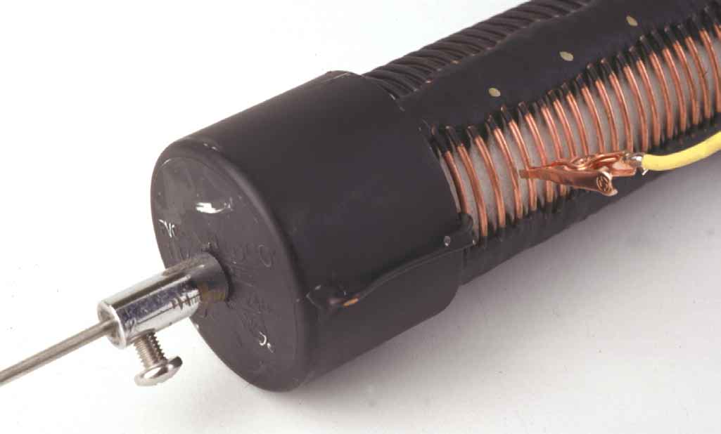
Close-up view of the matching coil. To the left is the 3/8-24 mounting bolt. Attached to the bottom turn of the coil is a length of shield braid used as a ground strap. A small area of the PVC pipe OD is ground flat to provide room between the coil turns and the pipe form for an alligator-clip tap to firmly grasp a wire turn without interference.
The loading coil resembles the matching coil except it has a greater number of turns. A RadioShack whip is attached to the top PVC cap. The wire lead connecting the bottom of the whip to the top of the loading coil passes through a hole in the top of the pipe cap.
Center-drill both end caps. Drill the top cap on the loading coil to accept a RadioShack replacement whip assembly (RS 21-952). In the matching-coil’s bottom cap, drill a hole to accept a 3/8-24 bolt for the mounting stud. Also, drill a small hole through the side of each top and bottom cap, near the top, to pass a length of #14 wire.
To the bottom of the whip and mounting bolt, attach 12-inch-long pigtails of #14 bare wire, passing the wires through their cap holes to the outside. These wires, respectively, connect the bottom of the whip to the top of the loading coil, and the mounting stud (RF feed) to a clip lead for the matching coil. Fasten the whip and the 3/8-24 bolt to their respective PVC caps, securing them tightly. Place a drop or two of thread-locking compound on the threads of the whip base in the upper cap and on the threads of the 3/8-24 bolt in the bottom cap. If either of those mounting nuts come loose once you have glued the whole thing together and wound the coils, you may— shall I say—utter a few words of disappointment! Once the connections are tight, align the flat sides of the two coil forms at the opposite ends of the main shaft and glue the entire shaft assembly. At this point, your creation starts to look like a real antenna!

Two of these reducers (Genova and DO-IT #30245) are needed to make the transition from 11/4-inch pipe to 1/2-inch pipe.
Now, wind the coils. Strip a 25-foot roll of #14/2 (with ground) house wire. Wrap the wires on their respective forms, holding the turns temporarily in place with electrician’s tape. The matching coil on my 20- through 6-meter antenna consists of 11 turns spaced 1/8-inch apart (a length of about 17/8 inches).
The loading coil has 25 turns spaced 1/8-inch apart for a length of approximately 37/8 inches. Wind the third wire on the antenna shaft, spacing the turns about 1 inch to 11/4 inches apart. Don’t wind the turns of the helix any closer than an inch apart, otherwise tuning the antenna on 10 and 12 meters will be a real challenge.
When the coils are wound to your liking, mix a couple of inches of epoxy putty and cut it into six strips. (Duro Epoxy Putty Sealant works well. I use the 30-minute variety and find that I have enough putty in one package for two antennas.) Roll each piece of putty into a bead long enough to extend the length of the matching and loading coils. Place three beads of epoxy on each coil, spacing them equally around the forms (but not over the flat areas). Lay each bead on its respective coil and press the bead until it flattens and contacts the coil form. When cured, the epoxy putty holds the coil turns securely in place.

Figure 1—Schematic (A) and pictorial diagram (B) of the $20 homebrewed mobile antenna. From bottom to top, the matching coil, main section, loading coil and the adjustable metal whip. Adjustable taps on the matching and loading coils are made with small alligator clips. See the Materials List before you go shopping.
Clip leads and cosmetics are next. Wrap the three-foot shaft and its winding with electrical tape. Spray the coils flat black taking care to mask the coil-tap areas above the flats. Solder a 6-inch-long clip lead to the 3/8-24 mounting-stud pigtail and a 12- inch clip lead to the top of the helically wound shaft cutting off any excess wire.
Connect the bottom turn of the matching coil to a length of 1/2-inch-wide copper braid to serve as a ground connection. Solder the top of the loading coil to the whip’s pigtail. Insert the whip and you’re ready to install the antenna, tune it and get on the air!

The main shaft of the antenna is wound with a turns spacing of no less than one inch.
Installation and Operation
I use a standard bumper mount with an extra ground lug placed a few inches away to which the matching coil’s braid is attached. Install the antenna and guy it—I use a length of 1/2-inch PVC pipe attached to the vehicle’s roof rack as a guy.

Table 1 Coil-Tap Positions and Whip Extension for the Mobile Antenna
Tuning
It helps to mark the tap points of the loading and matching coils for later reference. I use a gold-paint pen and place the marks on one of the flat beads of epoxy putty that runs the length of each coil. On my current antenna, I have dots placed every five turns and keep a small chart at the operating position. The reference points make band changes quick and consistent every time. The numbers in the coil-tap chart of Table 1 refer to the coil-tap points as counted from the bottom of each coil.
This antenna tunes 20, 15 and 17 meters easily with the whip fully extended. I find that I have to drop the whip into the shaft about one foot to tune 12 meters, and about two feet to tune 10 meters. Get out a note pad and a pencil to make a tap-point chart for the various bands. Connect an SWR meter in the feed line between your transceiver and the antenna. (If available, you can use your rig’s built-in SWR meter; my IC-706 is so equipped.)
Key your rig and adjust the power output of your radio for just a few watts. The SWR is most affected by the movement of the loading coil tap (the upper coil) and fine-tuned by the placement of the matching-coil (lower coil) tap. Table 1 provides some starting points for finding the lowest SWR on each band. Each installation is different, so don’t expect the number of turns given in Table 1 to match your installation exactly. Key the rig, check the SWR, move each tap up or down one turn and repeat the process until you’ve obtained the lowest SWR on each band.
On 20 through 10 meters, the antenna is 1/4-λ long. On 6 meters, the antenna is much too long to tune as a 1/4-λ radiator, but not too long to tune up nicely as a 1/2-λ radiator.
With the whip fully extended, it’s only a matter of some experimentation to find a “sweet spot” for 6 meters. (I wouldn’t be surprised to discover a multiple of 2 meters hiding in there somewhere, although I haven’t had the inclination to look for it).
The whip can collapse completely into the antenna shaft. This is great, especially if you keep your vehicle in a garage as I do. No matter how far into the shaft I retract the whip, at 100 W output, the dielectric and clearances are such that I have experienced no problems with whip-to-coil arcing.

A close-up of the antenna base.
Summary
Now go have some fun with your “$20 Martian Death Ray” (as my brother John,AB4GK, calls it). Just wait ’til the guys who ordered their expensive new HF mobile antennas hear from you tonight!1 And look for me on 17 meters. I’d love to be the first person to compliment you on your new antenna!
Materials List
Length of 1/2-inch-wide copper braid
3/8-24 mounting stud
25-ft #14/2 w/ground house wire
Two 11/4-inch PVC pipe caps
Two 11/4-inch to 1/2-inch PVC reducers
(Genova and DO-IT #30245)
36-inch length of 1/2-inch PVC pipe
PVC cement
Epoxy putty sealant
RadioShack collapsible whip (RS 21-952) Two alligator clips Plastic electrical tape
By Frank W. King, KM4IE
From QST April 2000